
In the recent Amped FIVE Update (7620), there were a number of enhancements all concerned with the Aspect Ratio of a digital image and the pixels that make up that image. In this series of posts, I will endeavor to simplify this subject with the aid of the new filters and features in Amped FIVE.
When developing Amped FIVE, a huge importance is placed on user flexibility. Can it do simple things quickly? Can it utilize advanced filters and algorithms? Also, can a user grow with the software to conduct higher level analysis and enhancement techniques as their skill level increases?
As a result, there are very few places where a user is restricted from performing a certain technique or applying a specific parameter. It is up to the user, based on their image assessment and the task required, to establish a process and then complete that process using the software.
During the implementation of the Aspect Ratio Filter, this user flexibility ethos was considered and, quite rightly, maintained.
You decide what ‘Output Aspect Ratio’ to apply. You decide how to rescale and what Interpolation method to use. It is up to you, the user, to utilize all the presented information and perform a process, based on that information.
It is, therefore, important to understand the complexities of Aspect Ratio and why the filter works in the way it does.
I have been looking at this for some time. I presented some initial research within the Amped FIVE training at the LEVA Conference in Clearwater, Florida during November 2015. It was interesting to compare the difference between downscaling NTSC analogue sourced footage to a 4:3 Aspect Ratio, against upscaling. But why do we have to do it in the first place?
It all comes down to the digitization of the analogue video signal coming from a source device – the camera. Yes, we really are still stuck in an analogue world. It will be years before everything starts off as a square pixel inside a digital camera.
Right now you are looking at a monitor, presenting pixels – and they are square. When you look at a digitized analogue video signal within a computer, you are looking at that image built with square pixels.
The original signal though did not start off as pixels. It was a signal of lines. During the Analogue to Digital Conversion (A>D), each line is sampled at a set frequency.
In PAL there are 576 active visible lines, NTSC has 486 active visible lines.
To conduct the sampling process, it is required to read each line at a certain speed. This is the sampling frequency.
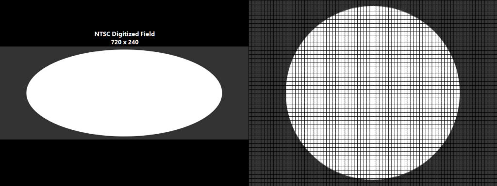
As each full line has a duration, it is possible to identify that each sample has a visual shape. This shape is not square!
But hang on, every pixel is square! Yes, that’s right; each sample gets squeezed into a square pixel.
In the above example (for demonstrative purposes only), we have 5 lines of samples that are slightly wider than they are in height. This is for explanation only as, if you remember, the signal is not separated until sampling and digitization have occurred.
For storage, each sample is allocated to one pixel. The result is that our digital representation is incorrect. Its Aspect Ratio, the correlation between width and height, is wrong.
Within the digitization process, the shape of how every pixel should appear, in order to replicate what was originally recorded, should be specifie. This is the PAR, the Pixel Aspect Ratio.
With CCTV, captured with an analogue camera and then digitized by a DVR. This is rarely reported correctly, if at all.
So, the pixels get stretched to the correct Aspect Ratio?…… Not exactly, you can’t change the shape of a pixel! What you can do though is remove, duplicate or interpolate pixels in order to take this correction into account and achieve the desired Display Aspect Ratio (DAR).
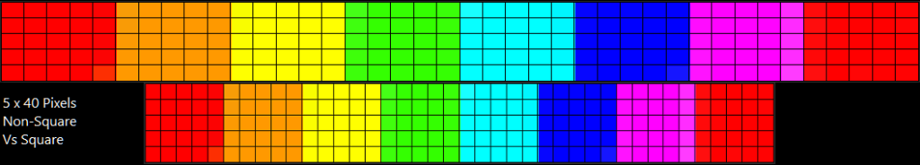
In Chain 1, we have three pixels of color. This is how they have been stored. However, we now know that we need to adjust the image for it to be presented correctly.
In chain 2, we have interpolated the three values to add in a new pixel in width. Our three pixels of color, now take up an extra pixel. If this were a shape, such as a circle taking up many pixels, in chain 1 it would be squished. After interpolation, our circle would be a circle again.
But look what’s happened. The green pixel has now been split into two, and its color is either half red or half blue.
It is vital to remember that this transformation of pixels is completed only to achieve the desired Display Aspect Ratio (DAR). Adjusting an image to achieve this will always remove pixels or add in new pixels, depending on your method of scaling. There is no way around this. The decision to add or remove will come down to the source signal type and the purpose of your analysis.
Identifying that your footage has come from an analogue source will usually come down to the dimensions of the stored pixels, such as 704 x 480 (NTSC) or 720 x 288 (PAL – Single Field). Interlacing may also be present.
There are a lot of numbers and math involved in the A>D Process.
The International standard for analogue video signal digitization, ITU-601, details the Sampling Frequency (SF) for square pixels and the sampling frequency of the analogue signal (described as non-square pixels).
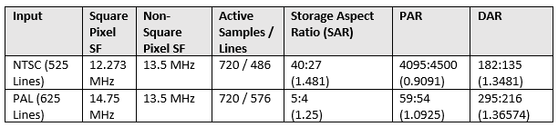
This chart displays some important information:
The PAR is calculated by dividing the Square Pixel SF by the Non-Square Pixel SF.
The DAR is calculated by using the SAR multiplied by the PAR.
From this it can be identified that:
- The PAR for NTSC is 0.9091
- The PAR for PAL is 1.0925
The result is that to replicate the original sampling, the width should be increased for PAL and decreased for NTSC. But, I will come more onto this later, as this decision will be based on your requirements!
The eagle-eyed among you will have spotted that neither output an image with a 4:3 (1.333) Display Aspect Ratio! What’s gone on there?
This all comes down to flexibility in signal fluctuations, processing and presentation. A bit of rounding down also has to occur to fit within the digital world and how a computer deals with the math.
The 4:3 Aspect Ratio has been the ‘shape’ of moving images since the early days of film. The decisions to use this ratio came down to a number of factors including, the physical size and cost of manufacturing the film strips, to being a compromise between a portrait and landscape image.
An important point to note is that the signal being processed does not have a DAR of 4:3, or 1.333. This is the processed signal – not the viewable area. It was decided that the ‘viewable area’ should be 4:3 and it is this area that becomes our digitized copy.
Now, after all that – how should we deal with this?
When conducting any analysis, it is vital that assumptions and guesswork do not interfere with calculations. If they do, they could affect further details that are reported as being fact. The challenge we, therefore, face as Forensic Image and Video Analysts, is that we have many unknown variables. As analysts, we must state these unknown variables, and be transparent in our decision making.
If we were dealing with a known analogue signal, from a known camera, and were then sampling and quantizing this signal into a digital form with a documented device, then it may be possible for us to define exactly what is required to present the image as it was originally captured. However, as we know, this is rarely the case.
We have unknown cameras, with unknown sensors. We then have unknown sampling methods, where the main consideration is the reduction in physical data size rather than retaining the original source. Has the sampling already taken the signal to pixel transformation into consideration?
Linked to these unknowns we have the different reporting of certain key pieces of information. Some are named differently; some are read from the stream, and some read from the container.
It can all get quite confusing!
Does Bill Murray look a little squished…? I think someone got their aspect ratio wrong!
In order to set a level playing field, at Amped, we have had to set some ground rules when it comes to the weird and wonderful world of Aspect Ratio.
Terminology
Note: you will see below that (unfortunately) there is some ambiguity on the SAR. SAR is used differently by different people and software packagesl. But they normally use the same acronym for two different concepts which are Storage Aspect Ratio and Sample Aspect Ratio.
(SAR) Storage Aspect Ratio
If an image is stored with 200 pixels in its width, and then 100 pixels in its height, then its Storage Aspect Ratio is 2:1.
Moreover, if an image is stored with 704 pixels in its width, and then 480 pixels in its height, then its Storage Aspect Ratio is 22:15, or 1.466 in decimals.
Alos, if an image is stored with 640 pixels in its width, and then 480 pixels in its height, then its Storage Aspect Ratio is 4:3, or 1.333 in decimals.
(SAR) Sample Aspect Ratio
This method of Aspect Ratio adjustment was developed for the MPEG4 container. The information is stored within each frames metadata. It is placed into the metadata at the time of encoding. The purpose of this value is to ensure that a decoder adjusts the video to account for how it has been sampled.
If an image is stored with a Sample Aspect Ratio of 10:11, and has 704 pixels in width, and 480 pixels in height, then a Display Aspect Ratio is able to be produced. How?
Width x 10 / height x 11 = 1.333, or 4:3
How about a standard PAL resolution of 720 x 576. If it had an SAR of 16:15, how should this be displayed according to the data?
720 x 16 = 11520, 576 x 15 = 8640
11520 / 8640 = 1.333 or 4:3
Any player being able to read the SAR will display the image either at 768×576, or 720×540. Both are 4:3, it will be up to the decoder to decide on the interpolation method (upscale or downscale).
(DAR) Display Aspect Ratio
The Display Aspect Ratio can be calculated automatically by the decoder, by using the Sample Aspect Ratio (mentioned above), the Pixel Aspect Ratio (mentioned next), or the value can be placed within the container as an instruction to the decoder.
In the case of a standard NTSC DVD, the pixel dimensions are restricted by this format to SD, 720 pixels x 480 pixels. To assist with Widescreen material, the format allows for a 16:9 Display Aspect Ratio flag. As a result, the decoder will interpolate the stored pixels to ensure that the width and height correspond to this wider aspect.
(PAR) Pixel Aspect Ratio
As we know, a pixel is a square, so it will have a ratio of 1:1. But we also know that pixels have to be adjusted to account for how the image has been created when it derives from an analogue signal or is within a format capable of analogue output.
A video recorded on your smartphone will have a 1:1 PAR
A computer animation, created for a PAL Video DVD, utilizing the Mpeg2 format, will have a PAR of 109/100 or 1.09. This would be calculated by using the image dimensions of 720 x 576, where the desired DAR is 4:3.
Finally, if the ITU-specified standards have been used in the digitization of an NTSC analogue video signal, the PAR used in the digitization is 10:11.
Now that we have established what certain terms mean, let me add in the final one:
Output Aspect Ratio
In order to avoid confusion and misinterpretation, the Aspect Ratio Correction Filter in Amped FIVE has a parameter called Output Aspect Ratio.
This can be entered as either a fraction, such as 4/3, or as a decimal like 1.3333
There is no other figure to enter.
No SAR or PAR…Why?
It is impossible to identify exactly how an image should be adjusted, purely by playing the numbers game. It is easy to understand that anything that starts off as an analogue source should usually be displayed at 4:3. However, how it has been created is an array of unknown variables. Also, we cannot revert the process.
We cannot assume that a device has followed the ITU-601 specifications. We can’t go back in time and capture the event using a standard device. Any adjustments we make; we make on the pixels we have now. If precise measurements, speed or motion analysis is required, then a full assessment is required of the equipment, and adjustments may need to be completed manually.
The Output Aspect Ratio is designed to allow the automatic adjustment of an images’ scale, to present an image with an aspect ratio closer to the original scene than that digitally captured, by accounting for the intended Display Aspect Ratio.
So, if the source digital data is 704 x 480, and it is interlaced, it has originated from an analogue camera and signal. As such this should usually have an Output Aspect Ratio of 4:3.
Choosing to adjust the Aspect Ratio, and then your method of Interpolation and which axis to retain (Height / Width) will be down to you.
It is time to take a break, and consider some of the issues discussed. In our next post, ‘Using the Aspect Ratio Filter’, we will go into how all the Aspect Ratio information is displayed, the filter settings, the methods of interpolation, and some practical examples of its use.
The fun part will be looking at how to achieve the final 4:3 Aspect Ratio. It is this stage that produces some interesting results!