Your hard drive is still spinning after installing our latest Amped FIVE update a few weeks ago. Here we are with an exceptional extra release for you. We are indeed making an exception to our release cycle to deliver a new feature that users have been eagerly waiting for. Welcome to Speed Estimation 2d filter!
The purpose of Forensic Video Analysis is to answer questions using imagery. Analysts get asked questions every day: what is the license plate of that car, how tall is that person, and… what is the speed of that vehicle?
There has always been a strong partnership between both the Forensic Video and Forensic Collision communities. Several years ago, there would be a requirement for the video to be acquired, analyzed and processed correctly by a video team before it could be used within a collision investigation. In recent years though, with the advancement of Amped FIVE allowing full decoding, analysis and science-based restoration and enhancement within a single application, most tasks can now be completed directly by the many collision teams using FIVE in their day-to-day work.
To further support this vital investigative role we researched several scientific approaches to the estimation of speed from video and the new filter introduced in this update uses 2 axis of measurement, hence the name Speed Estimation 2d.
It is vital that the video to be analyzed has full evidential integrity, in that it has not changed since the time of initial acquisition. This means that no transcoding has taken place during the export or any interim processing, such as within a proprietary CCTV Player or Digital Evidence Management System. Any changes may significantly alter pixel and timing information.
Once integrity and, of course, authenticity, have been confirmed, we must give several considerations to the video in the assessment of suitability for using Speed Estimation 2d.
- The vehicle must be travelling over a flat surface.
- It must be possible to visualize where the bottom of the wheel has contact with the flat surface.
- A rectangular reference object with known measurements must be visible on the same surface as the vehicle.
- A minimum of 2 video frames displaying the moving vehicle must be visible, although with this minimum value, the uncertainty will be very large. More frames allow for a longer distance travelled and therefore a lower uncertainty value.
- The frame timing of the video must be known and reliable.
We will take an in-depth look at the identification of measurements, the tracking of the vehicle path and frame timing whilst using the filter. Beforehand though we must prepare the imagery.
If the video is suitable, an important initial processing stage is the correction of any optical distortion. Objects that are straight in real life, should be straight in the image. The Undistort or Correct Fisheye filters, both found within the Edit category, will assist you in this task.

Following the analysis and visual interpretation of the imagery, any restoration and/or enhancement must be completed using the image generation model. For instance, it is important to identify a requirement to correct the Aspect Ratio, as this should be applied before correcting lens distortion. Several image processing filters can also assist in visualizing the path of the vehicle, such as Levels or Exposure.
Using Range Selector to select the portion of the video required, allows you to concentrate just on the vehicle, or vehicles, of interest. As you will see later, it is possible to individualize vehicle paths in a single chain. However, you may want to use separate chains: by copying & pasting a chain containing all the filters, including Speed Estimation 2d, you can select different ranges retaining the same image adjustments and measurement settings.

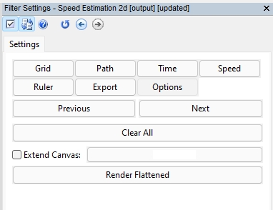
When the Speed Estimation 2d filter is selected, either by using the Quick Search bar or via the Measure category, the buttons will guide you through the workflow. The Help button at the top gives you workflow guidance, and there is a separate Help button within each section to assist you further.

By selecting the Grid button, you can start to set the measurements within the image.
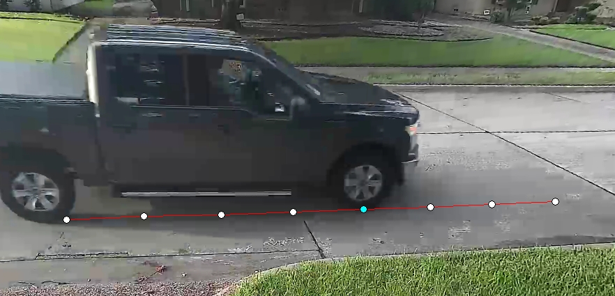
In this first example, we have a road segment that can be used for our measurements. Once the button is selected, your cursor will change automatically to the cross icon, indicating that you can enter points on the image. By selecting the four corners of the rectangle, the required grid will appear.
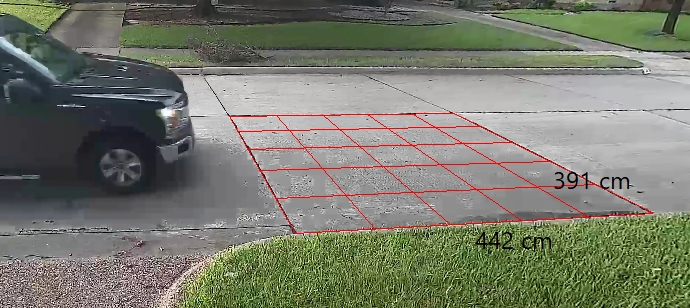
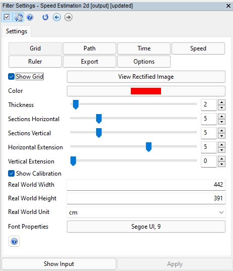
In the filter settings, checking both ‘Show Grid‘ and ‘Show Calibration‘ will enable the display of the Grid and the submitted measurement values onto the image.
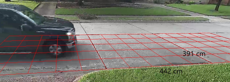
After the Grid is applied, it is possible to extend it using the Horizontal and Vertical Extension parameters. The extended lines are useful to ensure that other scene objects are correctly aligned. The extensions do not affect any subsequent calculations.
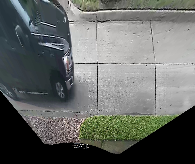
Another helpful tool within the Grid section is the ability to View Rectified Image. With the real-world measurements entered it will present the scene as an aerial image that has been geometrically corrected. This is particularly helpful for identifying differences between lens correction filters and the parameters used.
Lastly, what do you do if you have not got a rectangle in the image?
If the field of view, the camera and the recording equipment has stayed the same, it is possible to go back to the scene and place an object into the view. That video must then be exported in the same way as that of the original video evidence.
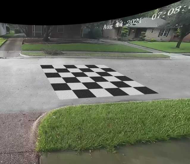
By placing a rectangular object, such as a floor mat with known dimensions, into the scene, you can obtain the grid measurements, and then copy the filter to the chain containing the footage with the vehicle of interest.
Hint: Using an object with high contrast patterning will help when visualizing lines.
You can also mix the two chains using the Overlay option within the Video Mixer filter.
Next, we have the Path button, where we will identify the movement of the vehicle.
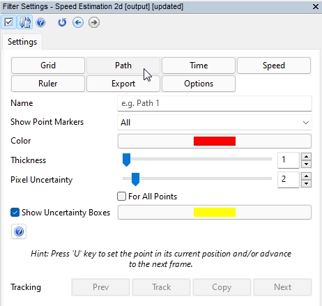
The points used must be on the same plane as the object measured using the Grid. So, this will be where the tire touches the road.
As you can select various vehicles, you can individualize them by using a unique name.
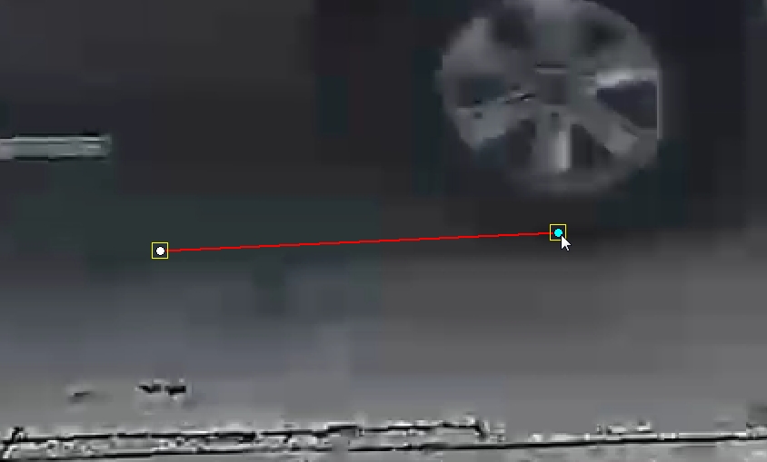
Placing the points is as easy as ‘zooming’ in with your scroll wheel to where the tire hits the road and then clicking your mouse. If you then press the U key, the video will advance to the next frame and a new point will be linked to the previous one using a line. You can repeat until you have finished your path.
You can go back and adjust the path points if required.
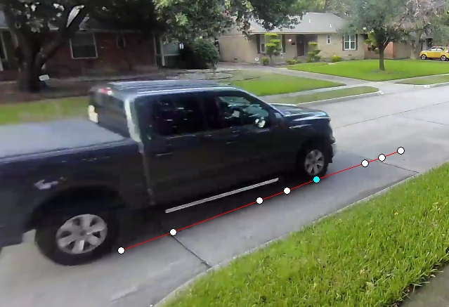
You can visualize only the point you have selected or all of them, and your selected point will be displayed in blue. You can also select a color and line thickness for the path of that vehicle.
The same value for Pixel Uncertainty can be set for all points, or they can all be different. This is important if some frames are blurred, or when a vehicle is travelling to or from the camera and the frames with the vehicle furthest away are more difficult to visualize.
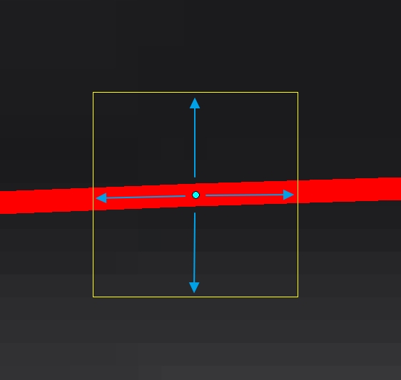
A yellow box will identify the Pixel Uncertainty for that point and in this example, we have used a 4 Pixel Uncertainty value on all points to allow for the effects of blocking compression.
You also have the assisted tracking of objects using the same technique as you would use if redacting a moving person in Annotate.
In certain situations, FIVE will be able to track the wheel and you can go back and move any points that need adjusting.
You can refresh your memory on assisted tracking by reading the blog post from its release: https://blog.ampedsoftware.com/2020/10/29/amped-five-update-18800-introducing-chain-folders-assisted-annotation-tracking-and-protected-pdf-reports/
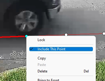
If the tire placement is obscured in a frame, you can remove it from the calculations by right-clicking and unchecking the option ‘Include This Point’.
After calibrating the image to known measurements and tracking the path of the vehicle, we must now divert our attention to the frame timing. To do this, simply select the Time button.
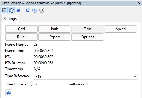
You will see your range Frame Number displayed along with various timing representations.
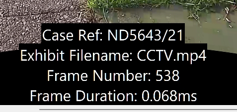
You may remember that we placed some text macros over the video at the start. To assist in the presentation, we can add more, such as the Frame Duration calculated from the Presentation Time Stamp (PTS).
If you are using a MPEG based video that is controlled by the Presentation Time Stamp, then this timing information will be displayed. You can refresh your knowledge on PTS timing with the recent Amped Blog detailing the adjustment of timestamps:
https://blog.ampedsoftware.com/2021/08/18/how-to-use-the-adjust-timestamp-filter-in-amped-five/
If you have a linked Timestamp, created using real-time by the CCTV system, then this information will also be displayed.
Next comes the selection of a Time Reference.
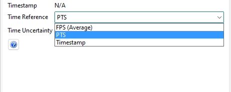
You can select from three data sources that can be used as a Time Reference.
FPS (Average): This uses the average frame rate calculated by dividing the total amount of frames in the selected range by the duration. Each frame’s duration will therefore be the same.
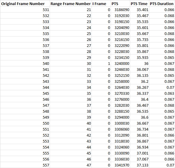
PTS: If a MPEG based video is used, and the Presentation Time Stamp is reliable, then this information can be used for the duration of each frame. We can see from our plotted path that the vehicles spacing is relatively even but when analyzing the timing information in the ‘Advanced File Info’, we can identify slight differences.

By opening the data in Excel, you can clean and sort the data for your task. It is now much easier to see the Duration pattern.
Remember, all of this timing and frame information can be overlaid on your imagery using the Add Text or Annotate macros.
Timestamp: A timestamp file can be used to control the frame rate of the video, but you may need to adjust the timestamp before using Speed Estimation 2d.
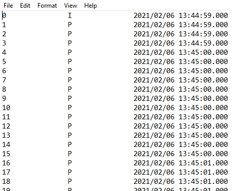
The above timestamp requires interpolating to ensure the milliseconds can be utilized. The Adjust Timestamp filter enables you to prepare the timing information for use.
Here is the link again to the recent blog post on adjusting timestamps: https://blog.ampedsoftware.com/2021/08/18/how-to-use-the-adjust-timestamp-filter-in-amped-five/
Often you will see a PTS pattern mirrored between the visual imagery and the timing pattern.
Take a look at the path points in this example that was captured with a different camera and CCTV System. There are 2 short frame durations and 1 long.
By analyzing the PTS data within Advanced File Info, the pattern can also be seen.

Lastly, within this section, we have the Time Uncertainty value.
Just as in the Pixel Uncertainty value in the Path section, there is a requirement to enter a value for timing errors. Very often CCTV systems will suffer from ‘clock drift’ that can cause millisecond differences between the image being captured and the time information relating to it. To account for clock drift on this PTS based system, we have entered an uncertainty value of 2 ms.
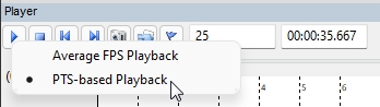
If you are using PTS, then it is a good idea to have PTS-based Playback. Just right-click the Play button to access Playback options.
If using a Timestamp, or the calculated average FPS, the Time Uncertainty value will be guided by your assessment of the frame capture and presentation.
To account for unknown variability, a general rule is that a higher presented frame rate will require a lower Time Uncertainty value. For example, half of the inverse of the FPS (0.5 x 1/FPS). So, if a video is presenting an image and timestamp every 1 second (1FPS), and an irregular pattern is identified when plotting the path of the vehicle, then a Time Uncertainty value of 500 ms may be considered.
However, if a video has 5 FPS, which would mean that each image would have a duration of 200 ms, a Time Uncertainty value of 100 ms may be considered.
For 30 FPS, you may consider 016 ms.
The establishment of timing patterns and intervals can be achieved using calibrated lightboards. Any error identified can then be entered for Time Uncertainty.

Here we have the standard lightboard, with the original image on the top, and corrected for analysis on the bottom. With large clear LEDs and both horizontal and vertical presentation, it can be placed into the camera’s field of view and a sample recording can be exported for analysis.
The frame captured here read 7.1 seconds with both the hundreds and thousandths columns presenting multiple LEDs.
Many Video Surveillance Systems record using a method called variable load. This means that frame rates can change dynamically on individual cameras if certain conditions apply. Therefore, the frame rate identified after an incident may be different from that at the time of the incident. Conversely, adding a lightboard close to a camera can cause a system to capture at a higher frame rate than at the time of the incident. A full understanding of the system at the scene is required to ensure the integrity of any identified values.
Please refer to your lightboard manufacturer, forensic guidelines and any local Standard Operating Procedures for further information surrounding lightboard use.
Timing accuracy is fundamental for establishing speed between neighbouring frames. When using many frames, however, minor imperfections tend to compensate for each other.
The filter, and the timing reference options, have been created in a way that allows you to use all three, and then compare the results. Simply Copy and Paste the chain, and select a different timing reference.
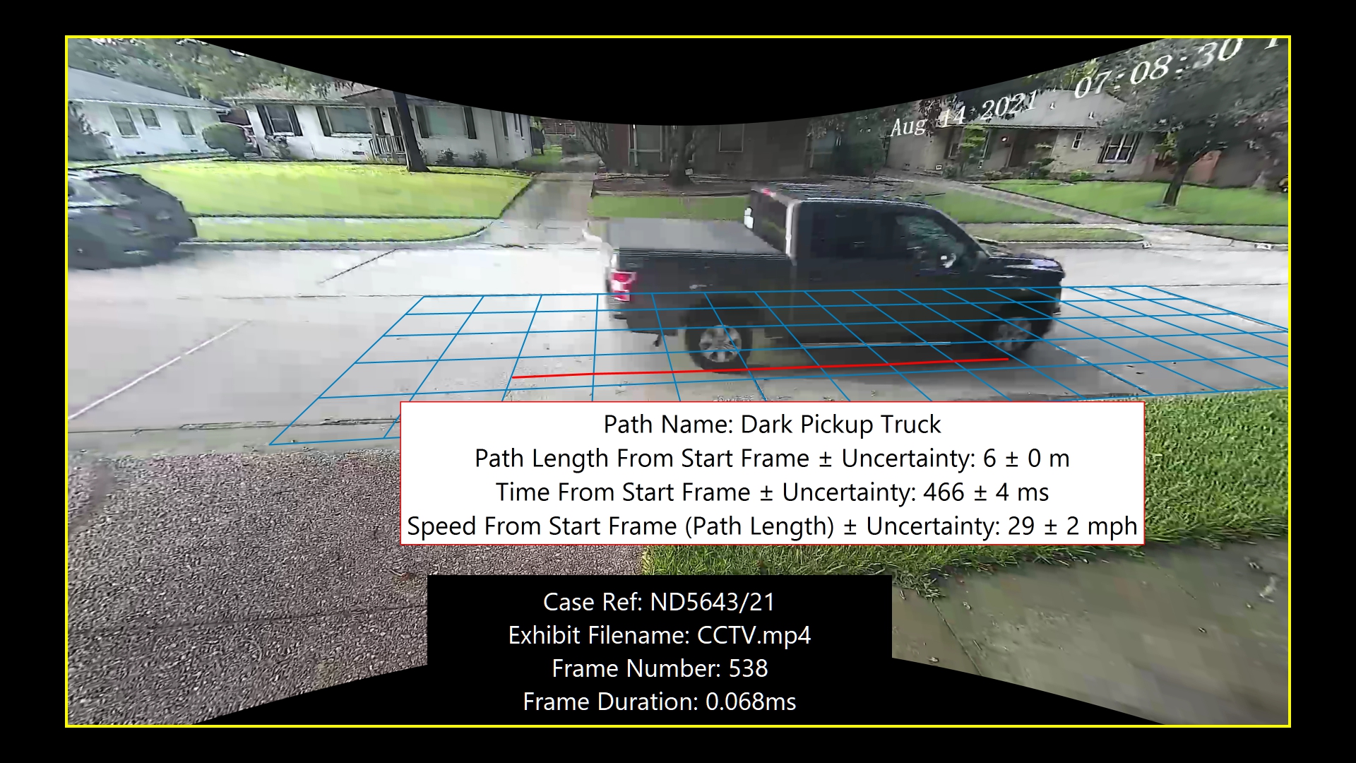
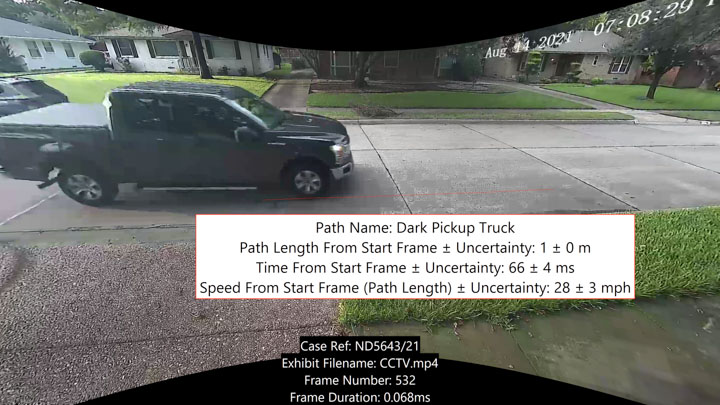
We are now able to use the scene dimensions, the path of the vehicle and the timing of the video to calculate many different values… including the speed!

Select New Measurement and an Annotation Text Box will appear over the image.
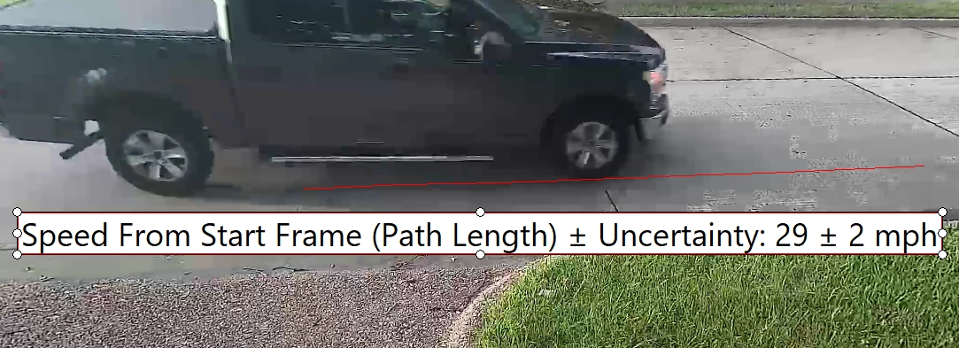
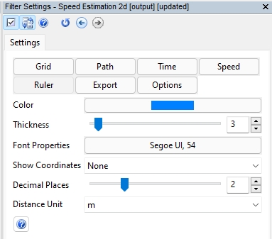
The settings applied here are the default, but these can all be changed, including the addition of further calculations using the Measurement Settings that are now available within the filter.
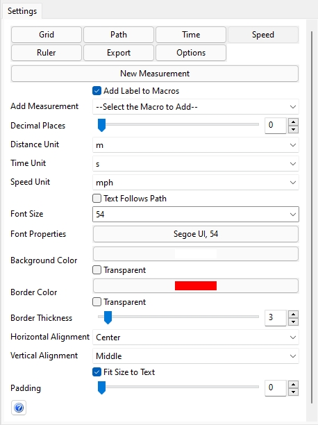
It is important to set your measurement units, along with how many decimal places you wish to present.
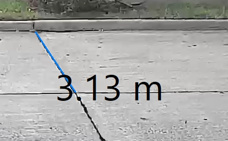
There is a checkbox that allows the resulting Text to follow the path of the vehicle and you can adjust all the text and box properties to suit the presentation of the evidence. A good idea is to use matching colors for the path and the measurement box.
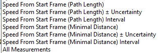
At the top of the settings you can find the measurement macro dropdown.
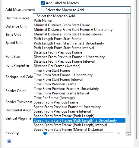
There are currently 27 different calculations that you can present. You can even select them all by using the ‘All Measurements’ macro, but that may be going too far!
By selecting the Textbox, you can enter the edit mode.
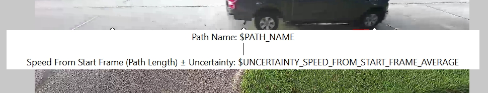
This enables you to enter your own free text, or simply select the required macros from the Filter settings. For those people who are used to the Text macros in Annotate, you will feel right at home here.
Each macro picks up the data for every frame used in the selected path and calculates the data dynamically for that frame.
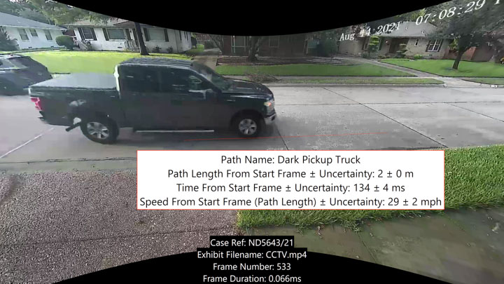
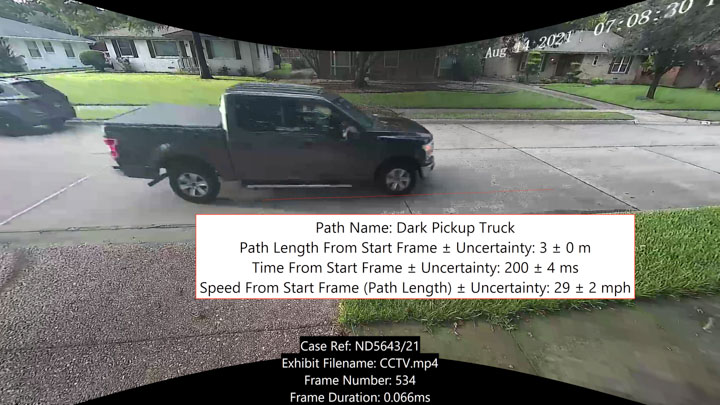
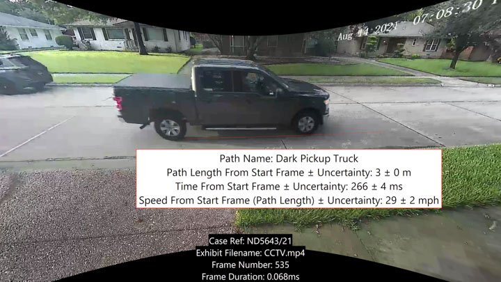
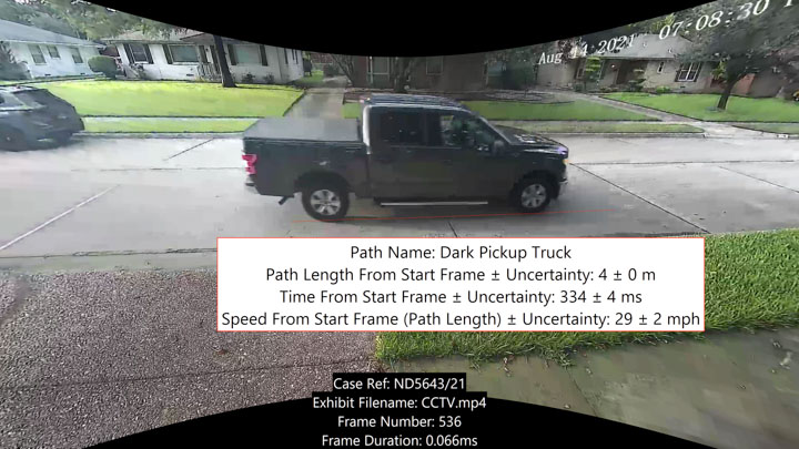
When it comes to speed estimation, there are two possible calculations: Path Length and Minimal Distance.
Path Length will use the distance and time between each point and then add all of the calculated values together. This is the recommended macro when the vehicle is turning in the frames you’re using for speed estimation.
Minimal Distance will use the distance and time between the first point and the last point only and this is normally preferable when the vehicle is traveling on a straight line since it gives you less uncertainty.
Next we have some tools to assist you.
The Ruler allows you to place measurements onto the same plane used for the Grid. These measurements are useful as a method of validation.
It is perhaps a good idea to use a different color to distinguish this from any path. There is a dropdown for showing the coordinates and these can either use the image pixel positions or the real-world dimensions.
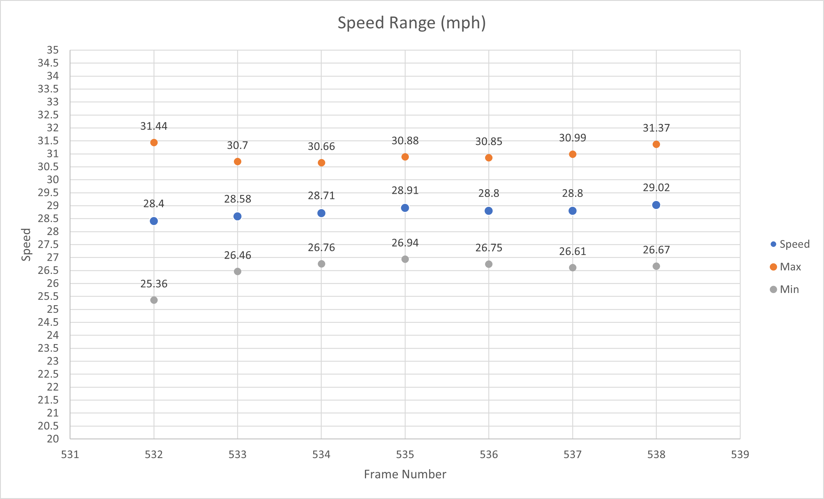
The Export button gives you access to all the calculations across all the frames.
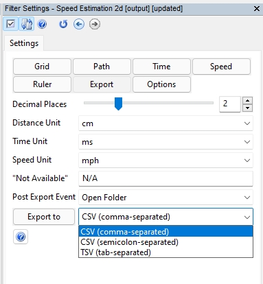
This is extremely powerful, as you are able to review all of the data in a spreadsheet format.
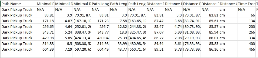
You can also perhaps mix this with information from the Advanced File Info, and create charts or data to suit your requirements.
Finally, we have the standard Annotation Options.
Having the ability to extend the canvas is very handy here as you may want to show the grid better and a certain part may be outside of the cameras field of view.
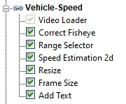
When it comes to presenting the imagery, your subsequent filter selection will be guided by the pixel resolution of your material after applying any lens correction, and then by your required presentation format. If dealing with 4k footage, for example, you may have to then downscale for an image sequence PDF. An example chain may look similar to this.
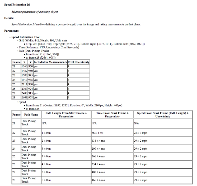
The Amped FIVE report will contain all of the values inserted and details of the macros used.
If access to the Video System is possible, calibrated speed runs can be completed and then the video exported for comparison against the calculated speed of the vehicle being investigated.
And there you have it, Speed Estimation 2d. Yet another filter to assist anyone in Forensic Video Analysis to make the complex calculations and presentation of vehicle speed so much easier.
But let’s make it even easier!
The Amped FIVE Assistant now includes a walkthrough for estimating the speed of a vehicle using this filter.
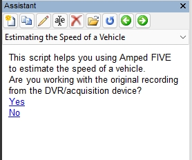
Remember that you can save a copy of the Assistant, edit it with your own notes or your Units Standard Operating Procedure, and then have that for future use.
To refresh your memory on how to edit an Assistant script, take a peek at this post: https://blog.ampedsoftware.com/2020/12/15/learn-how-to-create-your-own-amped-five-assistant-scripts-its-a-game-changer/
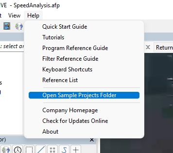
And that’s not all. You will also now find a Speed Analysis sample within the Sample Projects Folder.
In the coming weeks, we will be publishing another post going more in-depth into the calculations, macros, and algorithms used.
Bugs
We have fixed a few bugs for this release to avoid any delay in getting them to you.
- Range Selector: Improved the error handling when Lossless Trim cannot be completed.
- Annotate, Add Text: Fixed a bug that was causing the macros “Original Position in Time” and “Original Position in Frames” to always show value zero.
- Convert DVR: Fixed a bug that was inhibiting conversion when attempted for the second time, the issue was limited to a specific video format.
- Convert DVR: Fixed a bug that was causing an error message to be missing in the log file when transcoding audio to AAC format, with output to a separate WAV file.
- Tools -> Histogram: Fixed a bug that caused the “Show Saturated Pixels” feature not to work.
Don’t Delay – Update Today
If you have an active support plan you can update straight away by going into the menu About > Check for Updates within Amped FIVE. If you need to renew your SMS plan, please contact us or one of our authorized partners. And remember that you can always manage your license and requests from the customer support portal.